
A grateful reader has commented on the closed loop tuning post and asked about putting down my tune to help visualise the map better with numbers.
I really don't want to screen shot my tune as it's super tempting to just plug the numbers in and although it would probably work, it will certainly be different to what you need because my setup will be different!
So as a compromise, how about we go through the steps of setting up a base fuel map! That way you can set it up yourself and adjust it according to your setup as well as being able to visualise how the numbers go in the cells!
Let's have a look!
Creating a Base Map
Before making a map, make sure you setup your AEM FIC and AEM software correctly and apply an appropriate MAF clamp etc!
The quick and dirty way of putting together a base fuel map is through the AEM FIC's automated base fuel map builder. Copy a cal file and rename it as your new tune, then open it. With the new cal file opened, ensure that your X and Y axis are setup (if not, chart the map first!) and now right click anywhere on the map to bring up the context menu. In the menu select 'Create base fuel map'.

It will now bring up the create base fuel map window. In this window all you need to do is fill out the fields. If you've changed your injector size, go ahead and fill out the before and after capacities, if not, just leave these fields the same. Next fill out the expected max RPM of your setup and expected max boost.

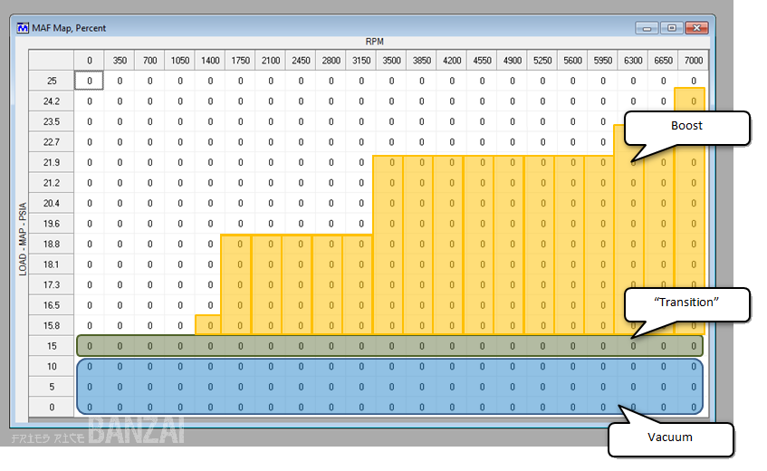
So if my setup will have a max RPM of 8,000 and a max boost of 20 PSIA (or 5 PSI boost, at sea level), I'd get the following base fuel map:

If you look at the map, it's quite conservative and assumes that you'll begin to max out your fuel input towards the higher end of the load (Y-axis) (e.g 83.6% more fuel). It's better to be overly rich, than over lean, especially in that region!
It also seems that the automated base fuel map accounts for possible over-boost or boost creep conditions (e.g. if your internal wastegate has potential obstructions preventing venting of exhaust gases) evident by the additional values pass the max boost value of 20 PSIA. Nice!
As you can see it already looks like the basic turbo map I depicted in the map charting article.

The main differences is that the AEM FIC automated base fuel map doesn't have a specific 'Transition' area as from 15 PSIA (read on the Y-axis) the values are 0 (i.e. do nothing) and the vacuum area is much larger (which gives you resolution to tune when not in boost).
What I like to do is to begin enriching fuel just prior to boost coming on in the 'Transition' area, more of a safeguard against a lean condition. Also, as we are using a piggy back system, we want to work with the existing factory computer and allow it to do its thing when not in boost, then help it out when boost comes on. Therefore, I don't usually have a large resolution for the 'Vacuum' portion of the map.
The automated AEM FIC base fuel map is quite handy to put together a quick map. Especially if something catastrophically fails and you somehow lose your tune but need to drive your monster back to the lab!
From here you can begin tuning..... But! Before we get into it, how about we look at the manual way of setting up a base map. Here's how I would do it!
First I would identify the maximum boost that the turbo will produce. In this example we have a max boost of 20 PSIA (or 5 PSI at sea level). From the AEM FIC Tuning Tips, a good rule to have around 125% more fuel at 30 PSIA. In our example of 5 PSI boost, this is quite small, so let's be conservative and pump in 50% at the turbo's expected max boost to make the AEM FIC hold the fuel injectors open for 50% longer time.

Tip! Rather than type '50' for each individual cell, you can fill the cells with the same value by fudging the 'calculate' function; here's how:
- First select the first cell you want to put a value in.
- Select the last cell and put that same value in.
- Highlight those cells.
- Right click the highlighted portion and in the context menu select 'calculate'.
- Smile


The calculate function fills the gaps by linearly adding the gap values. This is super useful so you don't have to calculate the gap values yourself.
Now we can look at the transition and initial boost PSIA break points. Now, boost will begin at around 15 PSIA (sea level). Search around the web for the atmospheric pressure in your locale to determine exactly what value it may be for you! At 15 PSIA, I want to begin enriching the fuel. So before boost, at say 13 PSIA, I'll add 3%, then at the boost, at 16 PSIA, let's put in 10%.

Now for the gap between the two, we'll do another calculate function as follows:

Then finally, we can do a calculate between the gap between the first boost break point of 16 PSIA to max boost at 20 PSIA.

And that's the manual base fuel map! The values are quite linear but that's fine because it gives us a working point. All this linearity will change once tuning begins and you won't be able to recognise your map after!
You can see that there is a significant difference between the manual method and the automated. The automated takes are more conservative view, while the manual method relies on the knowledge of the tuner to add conservatism.
So for fresh tuners, probably take the automated base map as it's very conservative hence more forgiving. If you know your setup and understand tuning, go ahead and create your base map manually.
Now it's time to tune.
Tuning
There two main aspects you should be looking at when tuning; target air-fuel ratios (AFRs) and power. So optimally you should tune on a dyno, but if not, you can roughly tune AFRs on the road.
First go on a conservative drive and check that motor performance under vacuum is unaffected. Then you can slowly begin going into boost (closed loop/open loop tuning).
Start with low boost in closed loop to ensure that you're going rich (e.g. 12, 11, 10 AFR). If so, then you can stop and go straight to open loop tuning. If not, adjust your map to enrich the low boost areas.
For open loop, do a quick full throttle run and make sure you keep an eye on your AFRs. If they get too lean, stop immediately and add fuel to the lean cells. If they are already rich, then good. You can then begin to tune at the different boost break points from the maximum boost down to the lowest boost pressure while in open loop. At each break point just aim to have a rich AFR (e.g. 12, 11, 10).
Let's take the manual base map as an example. During the full throttle runs I found that I was running too rich on the top end and too lean at the low boost areas. So I'll adjust these values.
A quick way to adjust cells, is by clicking a cell or highlighting a range of cells, then press CTRL-U (to UP the value) or CTRL-D (to push the value DOWN) at small increments. Remember to adjust bit by bit, but you'll get the feel for how much after awhile. Here's the updated map:

Once you have an acceptable open loop tune with rich AFRs, you can now go onto closed loop tuning which will more than likely touch the lower boost levels.
Basically follow the procedure in the closed loop tuning post for closed loop tuning:
- Setup fuel values in your fuel map.
- Perform run.
- Check target values (AFR, power etc)
- Adjust O2 map to minimise fuel trim fluctuations.
- Repeat from Step 1 until you reach your target values
Okay, so I do some closed loop tuning and I find that I still need to enrich the low boost portions. My updated map would be as follows:

Cool! Now it seems that I've finished tuning open and closed loop! I can now sit back and relax... not really. Although this tune will probably be fine. You'll find that the values will not only differ for the loads on the Y-axis but also RPM range in the X-axis.
This is where power runs come into play. When you jump on a dyno and tune for power, you'll find that at different RPM break points; you'll uncover lean/rich spots and power holes. So you'll then begin adjusting the tune for these. Bump up the cells for lean spots, trim cells with rich spots and have a look at cells that produce a flat power curve. Also note that you may also find that at some rich/lean spots it may actually make more power! It will then be up to you whether you adjust to hold your target AFR or to keep it.
So after doing power runs I find that I have a rich spot between these RPM values and adjust accordingly:

And then perhaps I want to be more conservative at high RPM values and to prevent pinging, I'll enrich the top end RPM cells:

So after several runs you can see that the map has changed significantly and you may recall the following pics from my previous posts:
The orange are the cells that were adjusted during tuning, with varying amounts of compensation. Quite similar to what we've done:

And as you tune, you'll begin to see the different zones I talked about in closed loop tuning.

So is that it? No...
Once you've got your fuel map to a generally acceptable tune, be prepared to mess it up even further! You will then need to tune the O2 map and possibly the ignition map and MAF map. Any tinkering in these other maps will require you to adjust your fuel map more. Any tinkering with your physical setup (e.g. new exhaust, new injectors etc) will again necessitate tuning.
As you can see it's quite hard work! But the more you do it, you'll get the feel for it and begin to understand your setup and what it needs.
Remember, piggy back tuning (especially O2 map compensation) is not easy. It's pretty dam hard. So persevere!
If you have any questions, suggestions or even like to share how you do your tunes, feel free to leave a comment!
Good luck!!

Pretty good stuff. What do you use to view your logs?
ReplyDeleteI think i would of been better if aem made a playback that overlays the map.
i try to screen record the laptop while tuning but i cant find one that is good enough.
Hey there! Yep good question! You can record runs using the record function in the AEM FIC software (currently called F/IC Calibration Software).
ReplyDeleteThere's a thunder looking green symbol (although I think it's suppose to look like a line graph) on the top menu bar, between 'undo' and 'settings' icons. This initiates logging to computer, when you click it, logging starts. The icon should then go red. When you click it again, logging stops and you are prompted to save a log file.
Then with that log, you can replay it back using the AEM data logging analysis software where you import the log and select which data to show (e.g. Engine Speed, AFR, O2 etc).
A little bit of a process but what you can do is go out and record a number of logs for the day, in a note book, note down any observations you had for each run (and make sure you tie it to the file name you saved the log as), then come home, do your analysis and adjust the tune where necessary.
To my knowledge, I don't think there is a quick method to bring up logs for the FIC unfortunately.
Yea I've done that before. I had a aem fic last yr. I change my setup this year and was looking for a better way. I found a guy on a crossfire website. He made a xlsx convert that plots the afr on top of the fic cells. I message him but he hasn't log on for at lest 3 yr.
ReplyDeleteWell i talk to some excel guys and i found out how to make the table i was talking about. I tested it off of a few logs i did and it work great.
ReplyDeleteHere is a screen of it. I still have some coding to do, since im adding a throttle position variable.
[img]http://i23.photobucket.com/albums/b381/xile6/RealAFR.png[/img]
Oh wow! Nice work! A pretty neat tool to accompany the AEM FIC! I wonder if you can market it back to AEM...
DeleteI posted it to the aem forums but no one seem to care. I think aem drop all supporet for the fic. I just use it to tune my car. It works great, and makes everything easy to see. The only down side is if I change the scale I have to redit the code. I'll post a drop box link for it later. IF you wanna check it out
ReplyDeletei would be very interested in learning how to setup the excel logger.
ReplyDeleteHey Banzai, real good write up. Followed the base map steps and now have my fic running larger injectors. One question for you, for the fuel map, couldnt you start the load axis at 12 instead of 0? I am of the opinion that the manifold will not see 12 psia at any time and hence we dont have to tune at that load. Is that a correct observation?
ReplyDeleteHi rowanta! Thanks for your question!! If 12 PSIA is your atmospheric pressure before boost, then if you start your load axis at 12, you won't have any cells/break points to tune in vacuum.. I guess really, you only want to tune the boost portion (12 PSIA and above) but without the vacuum portion, you won't be able to enrich the AFR prior to boost; you can only add fuel once it hits boost. In some cases you want to start adding fuel prior to boost, just within vaccuum. So it's usually a good idea to give yourself some room in the vacuum portion. So maybe have the first row as 0, second row as 6 then your third row as 12. That gives you two cells resolution to tune in vacuum. The more rows you give yourself, the more finer detail tuning in the vacuum portion you can do! Hope that helps!!
DeleteAnother reason is if you are running larger injectors. If you are, you will need to pull fuel out of the vacuum portion so the larger injectors flow like stock. Otherwise, your factory ECU is going to try to trim the fuel out and will either fail to run properly and/or trigger a CEL.
DeleteYuppers!! You're absolutely right!!
DeleteHi Fried Rice,
ReplyDeleteReading your superb blog. I want to tune in the closed-loop region, did you use the 1k resistor AEM mentioned in the manual , between your o2 sensor and the ecu?
Heya Robert!
DeleteOh good point! Yes I did!
When I was choosing the AEM FIC I went through all the info about with including installation. Some people were already utilising the off the shelf Boomslang harness that already incorporated the resistors with great success.
Initially, I didn't use the resistors and found that on occasion I would come up with a Check Engine Light (CEL). It turned out, it needed the pull-down resistors to ensure that when the sensor indeed read zero, it really meant zero. So I went ahead and did that; problem solved!
So you can be conservative and don't install the resistors and see how you go. If you're tuning well with no CELs then I wouldn't worry about the resistors. If however you are getting abnormal CELs (MAF, crank angle and/or O2), then try installing the pull-down resistor(s). It's not too difficult to do so anyway.
Good luck!
Hey there! Thanks for visiting! AEM did have a video tutorial on how to skew the O2 signal but it will definitely vary on car model to car model. I may do a write up on this but the basic steps consists of warming up the car then: monitor your long term and short term trims and your measured air fuel ratio, look at your O2 map and have a look at the highlighted cell. Gradually increment all the cells (highlight all) and record the changes to your trims and AFR. Do this all the way up and all the way down to build up a map on the response of your O2 sensor vs trims vs AFR. You can then use this to set your O2 sensor values based on when you go into boost. The issue you will have is that the O2 sensor is really fast and jumpy so you'll need to take this into account when tuning. Also, one of the other major hinderances will be trims. If the changes you make are really abrupt, the factory ECU may trim your changes out and back to the stock response, look out for this by monitoring trims. It's difficult because there is no one method to simply set your O2 map, you'll need to massage it according to your system. This was the most time consuming for my personal tune. Good luck!
ReplyDeletehowdy, Im building a turbo jeep wrangler. It is a MAP based system. Will the fic work if i'm not wired into the map sensor?
ReplyDeleteHey Paul! Yes, the AEM FIC has an onboard MAP sensor for tuning and by default it is configured as the primary load (basis for tuning). So you don't need to already have a MAP sensor on the car! Yay! You can however utilise your car's factory MAF sensor or even Throttle Position Sensor as the primary load but it those sensor inputs cannot really tell acurately if you are going into boost. MAF may see a lot more air but the issue is, it may not be design to have an output range that you can "see" more air; it may simply hit a peak. Then you'll need to know what does the peak represent; wide open throttle (atmosphere)? Below atmosphere (vacuum)? So it can be a bit difficult. Throttle position also doesn't help all that much as you can make boost at partial throttle. The AEM comes with a MAP sensor, so utilise it! You'll just need to plumb a vacuum hose to the motor!
DeleteGood luck!!
awesome for the info I thought that was case but wasnt sure. As far as modifing the tables and each save point are the current values changed or do i need to uplaod them each time i make a change?
DeleteHey Alex! When you edit the maps, it's all "live". So you don't need to save. You basically edit on the fly. This also means, you need to be careful not to type in the wrong value! Good luck!!
DeleteOk so I had a bit of a breakthrough with the FIC. From the beginning after I installed the unit the jeep would idle like crap. So I had been using the bypass in the mean time, until I was able to work on it. When just running the factory system the jeep idle controller would basically make it so I would have to two foot the jeep to keep from stalling. Well after reading some of your notes I was able to get the map to let the jeep idle a little smoother. This gave me enough time to look at the data and I had a bad inj driver from the factory. So as its a 4cyl i swapped over to another driver and it idles fine now in park. I was able to take it for a spin. With the FIC working the jeep goes into boost super fast and hits fuel cut. I also now still have same idle problem. Do you have an ideas on how to mod the map to keep the idle from dropping say, below 1000 rpm?
ReplyDeleteHey Paul! Excellent work on your break through! Do you have a wideband air/fuel ratio gauge? If it's idling at a low rpm because of the lack of fuel (lean); try upping fuel and corresponding O2 map when in closed loop. Alternatively, and possibly an easier tweak, does your Jeep have a throttle/idle control valve or screw? If you let in a bit more air you can nudge up your idle rpm. Good luck!!
DeleteI do have a wideband, the idle control on the jeep is computer controled. At idle the the fuel is fine, its on decel that it has issues.
ReplyDeleteHey Alex! Oh let me see if I get the picture. As you drive and begin to brake, the RPMs start to drop and so much so that the engine stalls/cuts out? During deceleration, does the Jeep stop injecting fuel and shows super lean on the wideband? Usually there will be a point that the engine will restart and inject fuel again. If it doesn't, perhaps check your blow-off valve; if it's on the "lightest" setting, it may not close quick enough and by the time that it does, the engine would stall. Also, check that the vacuum hose to the blow-off valve is secured well and ideally should be plumbed to a vacuum hose closest to the motor's vacuum path and not just tee-pieced to another device too far from the motor. It may not be tune related, perhaps it's a vacuum leak of some sort. Let us know how you go!
DeleteI seemed to have been able to fix it enough to drive it a bit. The fuel range the software was throwing out was -46 to 5.5 so at all points under 1000rpm i set to -15 and worked my way to the 5.5 i know this is a little rich but im still in the learning process
DeleteHey Alex! Good to hear! So you have bigger injectors? Just as long as when you started your map, all values should be a negative value to being your fuel back to stock. From there, you just need to add fuel when you go into boost or just before if you want to enrich it. Keep on playing! And it's always better to be rich than too lean!
Deletehttps://youtu.be/M3dl5gFPaGc
ReplyDeleteHello,
ReplyDeleteI have 2013 Honda Fit which I plan to supercharged later.
In preparation before supercharging,
I install FIC with boomslang harness so I can log it in natural aspirated condition.
I left all map at zero, but now at wot, the car won't go into open loop mode and stay in close loop. It also run a bit leaner and the midrange feel bit hesitant. I have not install the vacuum hose to FIC map input. Do you know is this is cause by the FIC don't have any map vacuum hose input? Or something else? I contact aem directly and according to them, even at zero map it don't meant the aem really not adjusting the output so I still need to tune it. Thanks from Howard
Hello,
ReplyDeleteI have a 2013 Honda Fit and I am going to install a supercharger soon.
I already install the boomslang wiring harness and AEM F/IC-6 with AEM UEGO because I plan to do logging while the car is still in stock(naturally aspirated) condition. so I connect the FIC and leave all the MAP at zero value... which should mean the FIC do not change any fueling/ignition parameter. The only thing I have NOT connect is the FIC MAP vacuum connection because I don't have any TEE fitting to tap into the vacuum hose yet...
The car run fine, but I do feel a slight hesitation in midrange acceleration compare if I use the bypass plug (no AEM FIC in the loop),
plus sometimes I got a lean OBD error code,
and I notice the fuel trim is a bit higher and when I do WOT, the scangauge still show the fuel trim number which must only mean the car do not go into closed loop function, right?
and the uego will be in the 15 to sometimes shoots to 16 range...(WOT)
do you know what went wrong? could it be because I have not connect the vacuum hose to the FIC onboard MAP input nipple?
I ask AEM directly and they say despite all values set to zero, the FIC might still modify the output and the only way to confirm is using oscilloscope which of course I don't have..
a friend of mine suggest that maybe the boomslang harness were wired wrong (some connection reguire tap but might be connected as intercept vice versa)...
right now, I am back to using bypass plug and everything run NORMAL... so this make me think that it can be the harness because if the harness is wrong then using a bypass plug would still create problem ...right?
please kindly advise me on this matter...
Thanks so much
Hey Howard! Hope you are well!
DeleteHolding all things constant, if you have the FIC installed but without the vacuum tube, it should be okay.. However, the vacuum tube is what senses the manifold absolute pressure.
The primary "load" or reference sensor that the FIC uses is the on board MAP sensor, which is what the vacuum tube connects to. Even if the RPMs go up, the FIC may not know what the reference is (as it is locked on atmosphere value, ~15). So you could try to connect the vacuum tube when you get the time.
Also, another thing that may make your system hesitate is the injector response time values and pre-setup in the FIC. If you haven't already, probably check that the injector response time in the FIC configuration settings is setup in accordance with your car. I'm not sure what the setup for the Honda Fit, but maybe check around forums. Should be in the micro-second range. If this isn't setup correctly, even if there is no change to fuel, the FIC may not be forwarding the injector pulses at the correct frequency which leads to injector pulse lags, creating lean conditions.
See how you go with that! Let us know how you go!
Good luck!!
hello fried.. can you tell me how to diy launch control on aem fic 6? using 12v dc input.. thank..
ReplyDeleteHi there! Unfortunately I haven't setup the launch control myself but I'm sure there are other articles out there. Probably start with the AEM forums!
DeleteWhat I recall is that with a 12V input, when that input goes high i.e. via a switch, you setup a tune that limits RPM.. But then once you launch, you need to set the tune back to your boost tune. From here, you'll need to check out other articles out there!
Thanks for visiting but sorry I can't help here! If I do happen to set it up, I'll definitely write a post about it! But not anytime soon though..
All the best!!
hi aem fic 6 got lunch contol???
ReplyDeleteHi Shah!
DeleteThe AEM FIC does have a 2 Step Launch Control capabilities, but it's more of a custom setup rather than a fully plug and play solution. As this function should only be used on the track and not on the street I haven't really dabbled in it much. Your best bet is to pop on over to the official AEM forums or have a look at other users and forums to see how they've set it up. It will vary from vehicle to vehicle but looking at the required inputs, it should be possible on most vehicles.
Good luck!!
Hi. I'm using the AEM Fic on a 2002 toyota Rav4, I have trouble with the O2 map, the toyota AF sensors before the cat converter have 4 wires, two for heating element and two for signal, I measure voltage on both wires, 3.3 volt on one and 3 volt on the other. I cant figure out how to connect and setup the O2 map. Do you know if the Fic is compatible wit this type og AF sensor?
ReplyDeleteSounds like a normal o2 sensor. One for signal voltage normally 1v-5v.
DeleteSignal output normally 0v-5v.
Then 12v heater.
Set the o2 map up as voltage
Hi there! Thanks for visiting! Hmmm, interesting; if you are getting 3V then it looks like you have a wideband O2 sensor. If it’s narrowband, then you’ll get something like 1V or less as it fluctuates constantly.
DeleteI haven’t tried it personally so you’ll need to hit up the AEM forums for more info but you should be able to intercept this signal as an input with the FIC. You’ll need to configure the O2 signal in the settings with the correct high and low voltages; most likely 0V-5V. You can test this by increasing and decreasing fuel and watch the values move.
As for wiring, the O21 wire should just connect to the +signal of the four wires. Check the manual. It shouldn’t need a resistor as that’s for a narrowband signal intercept.
Hopefully this will get you started! Let us know how you go!!
All the best!
does the aem fic go by CC's for injector size or a percentage between the stock and new injectors
ReplyDelete% of stock injectors.
DeleteIe
Stock 300cc new injectors 600cc
-50% to trim them to stock
Hey there!
DeleteYup, what you do is, when you’re setting up a new map, you can configure it to take into account a new injector size. You give it the original injector size in CC then give it the new injector size in CC and the software will linearly scale accordingly.
Also, in the Setup menu, you should ensure that the Injector Response Time is as per the new injector to ensure the FIC holds the injector in for the correct period of time. This varies as it’s really the lag between when the signal is sent to the injectors (very fast) to when the injector actually opens and sprays the fuel (delayed). That delay value is the response time. You can tweak this later but if you can, get it right now as it will affect your entire tune!
More info can be found in the AEM FIC user manual (its provided online, so feel free to have a look on the AEM website).
All the very best!!
hi, can this AEM FIC install into CAMPRO engine? have anyone done it before?
ReplyDeleteHey there! I’m not super familiar with the CAMPRO.. probably best to hit up the official AEM forums to see what they reckon.
DeleteIf it utilises similar signals for fuel injection, MAP/MAF and O2; then you should be able to manipulate fuel at least. The basic principle of a piggyback is to compensate the factory computer when you’re modifying your motor for performance but also maintain factory signaling such that the factory computer doesn’t get confused with the compensation.
If you want much more control over your motor, and especially if the motor is a bit finicky or if you don’t know how it will respond to a piggyback, then you may consider going stand-alone; here you replace your factory computer with a whole new manually programmable computer. A big investment as you’ll most likely need to replace the main engine wiring plus a complete make over with regards to factory tuning. In the long run though you’ll have far more control than a piggyback. Anyhoo, some other stuff to consider!
If your mods aren’t going to be so extensive and if your motor handles well with a piggyback, then piggybacks are really economical. Probably the main reason many people go with it.
All the very best!
Hi, I'm curious to know, should the FIC-6 run the engine as per normal if all trims are left on zero and it's fitted to a stock engine (no forced induction yet)? Just fitted to my 2TR-FE and it's running rich.
ReplyDeleteThanks, Evan.
Hi, I'm just wondering if the FIC-6 should run the engine as standard if no trims are moved from zero and no mods have been done to the engine yet? I have a 2TR-FE that I just got running via the FIC-6, but is running rich and hunting off idle. Have not set Inj. cc (unsure of OEM size) on PC,and no o2 wires connected off FIC-6, not sure if I need to?
ReplyDeleteThanks,
Evan.
Hi. I have a problem because I have an AEM FIC 10-1910 and I want to use it in a new project with HONDA D16A9 which uses ECU OBD1. I read that this model does not apply then the question is can not do something so that it can work like 10-1911?
ReplyDeleteHey bud,when I chance fuel injectors bigger size I'll put the new cc and old cc it's gonna gave me negative number what else too do,car has a tune do I need too do another tune thanks
ReplyDeleteHeya!
ReplyDeleteIf you’re getting a negative number it’s because the new injectors are bigger than the current or.. you might be putting the new injector size in the current injector size. Remember, if you have bigger injectors, it has more capacity so you need to REDUCE your maps (negative values) to bring it back to neutral. Conversely, if you put in smaller injectors, you will get a positive value because you need to work the smaller injectors harder to supply the fuel needed in the map!
If the new injectors are permanent, then no need to create a separate tune, the fuel injector adjustment will be global. But always save a copy of your current tune anyway, just in case!
All the best!!
Hello can i get your contact fried rice :D
DeleteHeya! If you have any questions, post it up here so we can all learn! You’ll find a lot of people have similar if not the same queries!
DeleteThanks!
Hello bud,now with the new injectors the idle is good bud when I hit gas slow it chocked at 1000 or 1500 rpm,but at 2000 rpm over it seems fine but my afr gauge is at 10.7 or 11.o at idle help please thanks
ReplyDeleteHeya! Idle you want to aim for stoich at 14.6 AFR. 10-11 is pretty rich for idle. If it’s stumbling at 1000-1500, I’m guessing it’s too rich for idle. Back off the fuel at those RPM values.
DeleteThe fuel injector conversion is linear, but in real life it’s never so. And you can expect to make little adjustments like this especially during your idle and cruising RPM/loads.
Aim to get a stoich idle first, then slowly test your acceleration and monitor your AFR as RPM and loads increase. It’s safe to go rich as you accelerate, you can always trim the fuel back.
Remember, work with your factory computer! Let the factory computer do it’s thang anytime you are not in boost. When I’m boost, or when you want to deliver more fuel, take over using the AEM FIC. If you try to take control of everything, it gets very complicated and you may as well get a stand-alone computer to give you better control.
If you find your fuel map not “sticking” and the AFRs seem to go back to certain values; make sure you’re adjusting your O2 map to compliment the fuel changes.
All the best!
Hi
ReplyDeleteIs it normal if the FIC adds fuel to the injector and cause the injectors to maxout at 100% duty cycle? Lets say i need a 34lbs injectors for my setup on 80% duty cycle, what i have now is a 27lbs injectors,if the FIC increase the fuel on the 27lbs injectors, it will probably max out the injector to 100% cycle. Is this ok?
Hi there!
DeleteIn short, naw, it’s not a good idea to max out your injectors. It doesn’t leave enough duty cycle buffer in case the factory ECU need to compensate for an extra lean condition.
The AEM FIC will respond to whatever map you have programmed. If your fuel maps is adding fuel and your injectors are maxing out; what does your air/fuel ratio look like? Are you too lean, too rich or just right?
If you are too lean or if you are just right, your injectors are under sized and you should upgrade. It’s usually not a good idea running injectors at 100% duty cycle; this means the injector is holding open and continuously spraying fuel. It should always have a moment to pause and you should have a buffer of duty cycle to ensure your injectors can keep up with fuel demands. It’s hard to tell exactly the number but keep a conservative buffer of 70-80% duty cycle as your “max”.
If you are too rich, then cut back the fuel and see what’s your injectors are doing.
Remember, there’s lots of variables that affect how much fuel the factory ECU is delivering and hence what the AEM FIC is augmenting based on your fuel map. Environmental factors like temperature, altitude etc will cause different air/fuel conditions so you need to have a duty cycle buffer with your injectors to ensure that you don’t get maxed out in a lean condition.
All the best!!
Ok i see, and how do you capture the afr data, boost and horsepower data on particular break point? Everything seems to move so fast on my gauge
ReplyDeleteHey there! Indeed it is!
DeleteThat’s why you need a controlled environment such as a dyno. You can run the motor at a particular throttle and tune your curves far more accurately than on the road.
The other technique is to log your data and do post run analysis. Create a baseline tune, plan your runs, determine what aspect you are tuning for (e.g. acceleration, cruise, stopping, traffic etc), record a number of runs labeled appropriately with the same conditions, then analyze the data. Are you hitting your target AFRs? Is your O2 map dialed in such that the factory ECU is not overly correcting your changes between runs?
The AEM software log reader can plot against different data points and you can see where they are sitting against each other. RPM can AFR, RPM vs O2, TPS vs AFR.. etc.
The only thing you cannot tune accurately for is torque and power on the road. If you are hitting your target AFRs, you should be pretty good.
With a stable tune, book in for a dyno and then hit those power curves then!
All the best!
I got my unit today, so basicly if i set all values to zero, the car will run as it was running with no piggy back.Nothing will change. Is this correct?
ReplyDeleteHey there! omg didn't even get a notification on your comment! Sorry for the super duper late reply! But yes! PROVIDED you calibrate the unit correctly and that you are not using any new aftermarket parts that will change the factory tune of the vehicle.
DeleteZero is your baseline. Adding will add to the factory signal, subtracting will reduce the values of the factory signal. So at zero, it should just be a pass through.
But again, go through the calibration steps to ensure that the FIC is setup according to your vehicle!
All the best!!
Hi i tried logging my setup, the afr signal is kinda late on the log data, is this normal? Lets say on particular time when i increase the tps and load the afr data woull be late a few miliseconds after the load.
ReplyDeleteHey there!
DeleteMakes sense! You can’t expext exact and immediate response. There are losses to be had and by the time fuel is burnt and expended as energy, the excess fuel measured in the exhaust will lag a tiny bit!
As long as overall, you are not overly lean in any break point.
All the best!!
Hi, have you setup the acceleration enrichment setting? According to AEM it will help on throttle tip in and hard accleration, the instruction given by AEM is confusing.
ReplyDeleteHey there! I haven’t used it personally either.
DeleteHaven’t found the need to.
If you’re having issues on hard acceleration, a common cause is that you may not have tuned for it in your maps.
If you’re at a particular break point, say idle, and then suddenly hit the throttle; you’ll find yourself in a region of your tune that doesn’t get used as often as stead acceleration.
.
Start with a rich map, record a few logs of abnormal acceleration scenarios and see where your AFRs are unstable. Make some observations in your run as well, was there hesitation? Or was it good?
Get your basic map down and then look into more specialised augmentations to refine your tune.
Good luck!!